The microstrip line is the most widely used interconnect at radio frequency RF and microwave frequencies. Hope it would be useful.
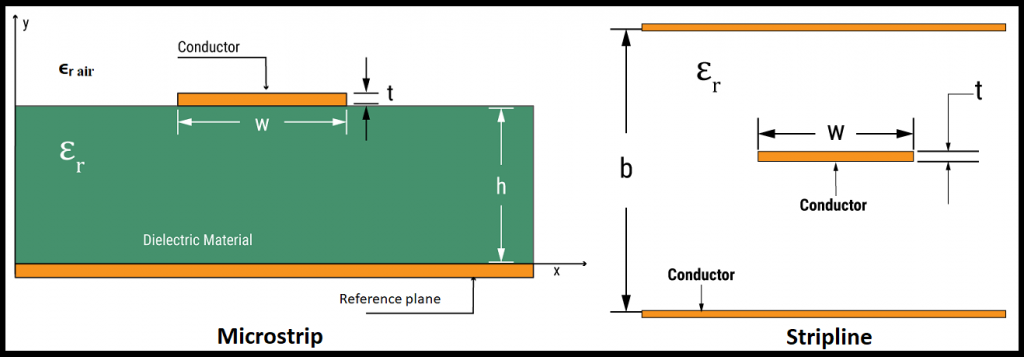
What Is The Difference Between Microstrip And Stripline Sierra Circuits
Because of the symmetry unbalance in Microstrip all discontinuity elements possess.

. International Journal of Electronics Volume 46 1979 - Issue 2. For example a 2 inch microstrip line over an Er 40 dielectric would have a delay of about 270 ps. A microstrip transmission line can be designed on the different configuration of the substrate layers which may be single double or the multilayered material.
It also increases the parasitic inductance associated with via holes. Thanks in advance. Show all volumes and issues.
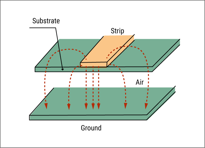
Microstrip consists of a strip conductor land on a dielectric substrate backed by a ground plane that radiates when the spacing between the ground plane and the strip. The key equations are Z0 L C εe C Cair and for the air-filled microstrip line with a TEM mode vp 1 LCair c. When microwave engineers refer to microstrip design they are referring to the design of RF and microwave circuits using the major types of planar transmission line technologies.
Technol kanpur-208016 india source microwaves. A Designers Guide pp69-166 RB. It is routed on the PCB surface and surrounded by two environments.
Best practice is to ensure the ground reference plane extends by a minimum of 3H on either side of the surface microstrip trace. Also assume that μr 1 which is the default if not specified otherwise and also that L does not change if only the dielectric is changed. 3 method c are gene of papers appeared form exp and com The cl reported Wheeler for Wh microstr reported work results.
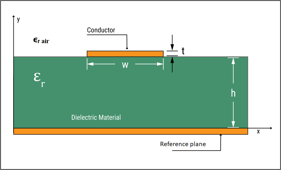
The microstrip line will be designed on a substrate with a dielectric constant of 102 and a height of 127 mm at 50 GHz. Fig1 microstrip line Microstrip line is used to carry Electro-Magnetic Waves EM waves or microwave frequency signals. Note to MMIC designers.
A designers guide to microstrip line. A designers guide to microstrip line. Terminate the transmission line in its characteristic impedance when the one-way propagation delay of the PCB track is equal to or greater than one-half the applied signal risefall time whichever edge is faster.
Discussions center on loss circuit Q dispersion dimensional ratios and moding. Engelmann from the Federal Telecommunications Laboratories of ITT presented as a competing printed circuit line. The width of the microstrip is designed for 50 Ω and the length for a 180 degree phase delay.
Introduction to planar transmission lines. See Figure 1 below. Trivedi A Designers Guide to Microstrip Line Microwaves p.
Model of microstrip line showing cross-section. Table of contents Volume 16 Issue 5. Provides information on how to design Microstrip Line with many feeds and have even given details about Patch Antenna by comparing various other feed types.
Increasing the height of a microstrip substrate decreases metal loss proportionately. A microstrip line is single-ended 1 in the sense that the conductor geometry is asymmetric and the one conductor namely the ground plane also normally serves as ground for the source and load. In most practical cases the dielectric substrate is electrically thin that is h λ.
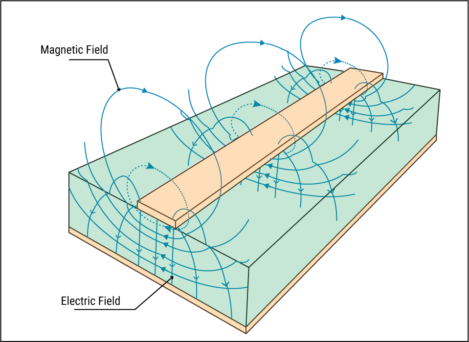
Probably the main advantage of microstrip historically is the ability to use just a 2 layer board with all components mounted on. The model assumes a Quasi-TEM mode of propagation and incorporates the effects of dielectric and conductive losses. In a microstrip line the wave-.
A Designers Guide To Microstrip Line Equations data and conclusions from many sources are compiled to define transmission characteristics. This document is rarely available and obtained after a great effort. You may find that a two-mil substrate gives more gain than a four-mil substrate for the same active device because of reduced inductance and in many cases that extra gain will offset the loss.
Microstrip Transmission Line Construction. Since it is an open structure microstrip line has a major fabrication advantage over stripline. It also features ease of interconnections and adjustments.
Submit an article Journal homepage. PCB material and air. 31 Views 3 CrossRef citations to date Altmetric Original Articles A microstrip design guide.
This article describes microstrip line basics and mention types of microstrip lines and their advantagesIt covers microstrip line striplinesuspended stripline slotline coplanar waveguide finline along with figures. The first Microstrip developments were done shortly after the appearance of Barretts article in 1952 by DD. It consists of 3 layers conducting strip.
Nov 9 2009 2 R. With the development in the technology and the need of the system-on-chip SOC requirement the use of the multilayered substrate has increased at high frequency. A designers guide to microstrip line.
Waterhouse Probably one of the most researched areas in the history of microstrip patch technology has. Easy to feed coaxial cable microstrip line etc. The microstrip line is a transmis-sion-line geometry with a single con-ductor trace on one side of a dielectric substrate and a single ground plane on the opposite side.
It also features ease of interconnections and adjustments. The display of the. Terminate the transmission line in its characteristic impedance when the one-way propagation delay of the PCB track is equal to or greater than one-half the applied signal risefall time whichever edge is faster.
The first Microstrip developments were done shortly after the appearance of Barretts article in 1952 by DD. Microstrip has conductors embedded in two dielectric mediums and cannot support a pure TEM mode. Then the transverse field is dominant and the fields are called quasi-TEM.
The tables of contents are generated automatically and are based on the data records of the individual contributions available in the index of the TIB portal. A microstrip design guide Search in. Trivedi dk indian inst.
The spacer material is typically a low-loss dielectric material having permeability approximately equal to that of free space. The basic model of a microstrip transmission line is shown in Fig. The microstrip line is a planar transmission line that is used prominently in RF and microwave circuits.
Joined Aug 19 2009 Messages 51 Helped 28 Reputation 56 Reaction score. Roxxon Member level 2.

Amazon Microstrip Patch Antennas A Designer S Guide Waterhouse Rod 9781441953384 Books

High Speed Design Guide In 2022 Design Guide High Speed Pcb Trace
What Is The Difference Between Microstrip And Stripline Sierra Circuits

Amazon Microstrip Patch Antennas A Designer S Guide Waterhouse Rod 9781441953384 Books
Pdf New Design Formulas For Microstrip Transmission Lines Using High Dielectric Substrate

A Designer S Guide To Microstrip Line Pdf Document
What Is The Difference Between Microstrip And Stripline Sierra Circuits
What Is The Difference Between Microstrip And Stripline Sierra Circuits
0 comments
Post a Comment